Case Study · Automation Industries

Coordinate Extraction for Pick & Place on an Automated Roll Forming Machine

A vision system verifies geometry and extracts X, Y position, angle and diameter across nine component variants, passing the data straight to the line PLC.

Industry

Automation Industries

Application

Vision system to extract co-ordinates for pick & place operation

The Application

Recipe-driven coordinate tracking across nine component variants

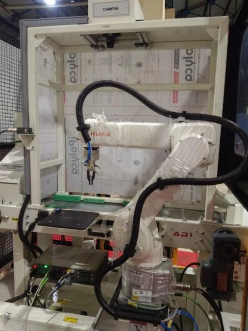
Deployed on an automated roll forming machine, the application verifies complex geometric configurations — tracking X, Y positions, orientation angles and custom diameters across nine distinct component variants — and reliably differentiates compliant (OK) from non-compliant (NG) part runs.
The primary application is to extract the coordinates used for the pick & place operation.

Key Factors

Performance at a Glance

Nine variants, one recipe-driven system

9

Distinct component variants handled.

8–24

Path-counting edge-finder filters, depending on the loaded recipe.

X · Y · ∠ · Ø

Position, angle and diameter data pushed to the line PLC.

Operation

How the inspection works

The captured image is analysed instantly by the vision software, and results go straight to the line PLC.

01

Instant image analysis

Dynamic path-counting edge finders analyse the captured image, using 8 to 24 path filters depending on the loaded recipe.

02

Verify against criteria

Structural features are checked against the inspection criteria defined for that profile variant.

03

Coordinates to the PLC

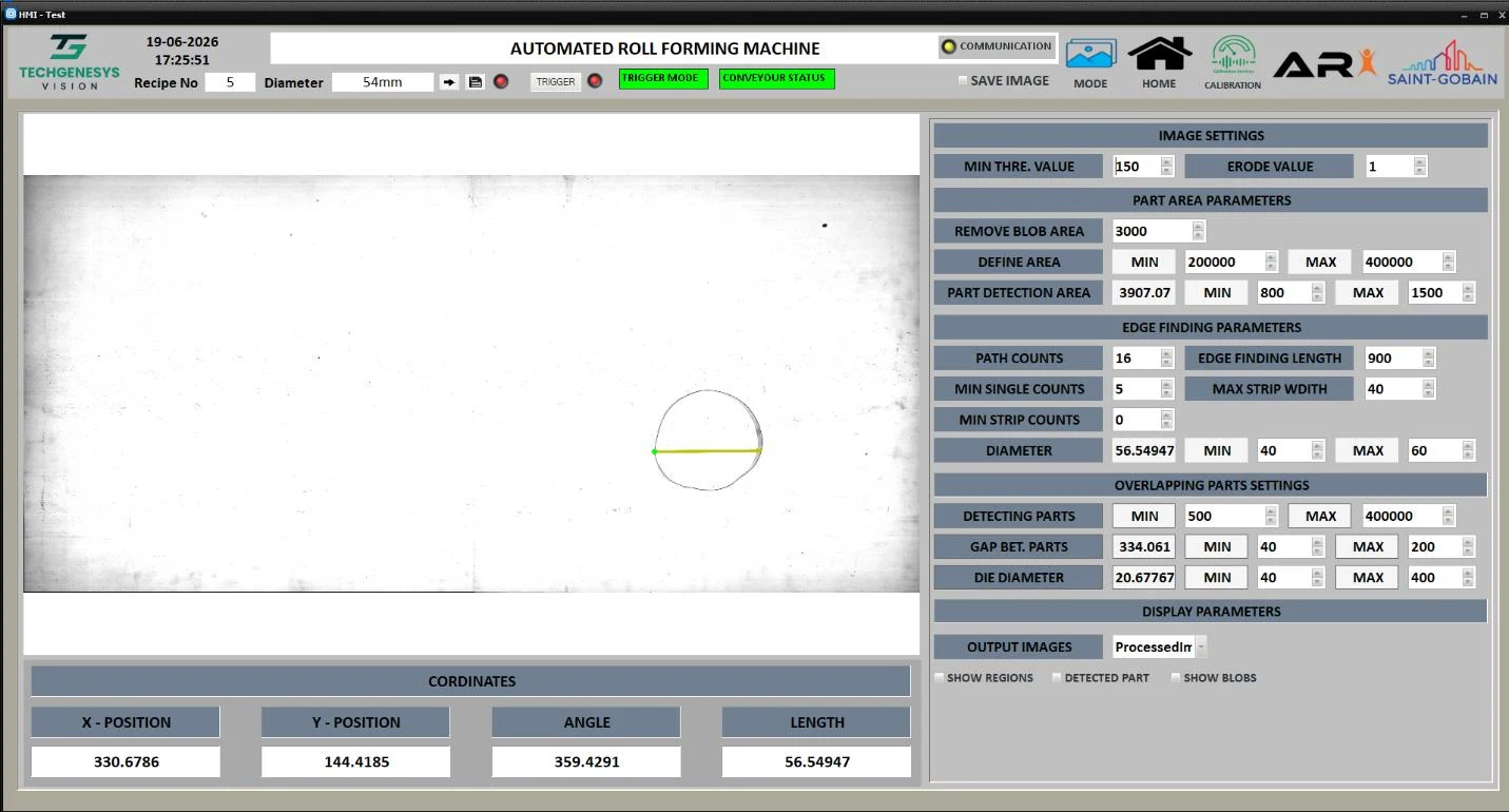
Within tolerance (OK), the X and Y positions, angle and diameter are sent to the line PLC and shown on screen.

04

Flag anomalies

Dimensional drift, overlapping anomalies or an empty conveyor are flagged for line adjustment or operator attention.

Final Result

Coordinates and dimensions displayed per recipe

Automated roll forming machine HMI — X / Y position, angle and length for pick & place

Technology Used

Hardware behind the inspection

Basler 20 MP Camera

Captures the component image used to extract coordinates.

25 mm Lens

Optics for the pick & place field of view.

Get Started

Have a similar inspection challenge?

Share your part image, defect details, cycle time, accuracy requirements, and existing machine information. Our application team will help evaluate the right machine vision architecture for your production process.

Book an Application Consultation

Share your requirement, our expert will be in touch with you on same day