Case Study · Automotive · Robotic Dispensing

Vision-Guided Robotic Dispensing of Square Beads, S Beads and Dots

A vision system locates multiple objects, extracts their coordinates and guides a robot to dispense onto each feature — then checks bead width and area for an OK / NOK result.

Industry

Automotive

Application

Vision system for robotic dispensing

The Application

Real-time visual feedback for precise, adaptable dispensing

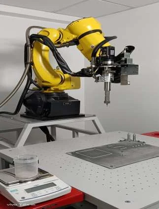
In the automation industry, a vision system in robotic dispensing enhances precision and adaptability by providing real-time visual feedback, allowing robots to recognise and accurately dispense materials onto varied shapes and sizes.
The primary goal is to locate the objects, extract their coordinates and dispense a solution onto the square bead, an S bead and the dots based on those coordinates.

Key Factors

Performance at a Glance

Three dispensed features, located and verified

3

Dispensed features: square bead, S bead and dots.

20 MP

Camera with an 8 mm lens over a 300 × 300 mm white light.

OK / NOK

Decided from the width and area of the dispensed solution.

Operation

How the inspection works

The camera provides the robot with exact positions, then verifies the dispensed result.

01

Locate objects

The camera captures detailed information about each object’s position and characteristics.

02

Extract coordinates

The system extracts accurate coordinates for the square bead, S bead and dots.

03

Robotic dispensing

The robotic dispenser uses this data to dispense the required solution precisely.

04

OK / NOK check

The width and area of the dispensed solution are assessed — OK if they meet the criteria, otherwise NOK.

Final Result

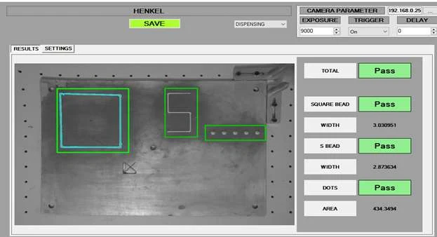
Dispensed features measured and passed

Result screen — square bead, S bead and dots Pass, with measured width and area

Technology Used

Hardware behind the inspection

20 MP Camera & 8 mm Lens

Locates multiple objects and extracts their coordinates for the robot.

White Square Light (300 × 300 mm)

Even illumination across the dispensing area.

Aurora Vision Runtime

Runs the locating and measurement program, communicating via PLC and LabVIEW.

Get Started

Have a similar inspection challenge?

Share your part image, defect details, cycle time, accuracy requirements, and existing machine information. Our application team will help evaluate the right machine vision architecture for your production process.

Book an Application Consultation

Share your requirement, our expert will be in touch with you on same day